![]()
![]()
![]()
![]()
Replacing IEEE-1394 (Firewire) controllers (and associated repairs) on main PCB of Nikon Super Coolscan LS-8000 and LS-9000
This seems to be a relatively common failure mode of Nikon Coolscan LS-8000 ED scanners, much less frequent in LS-9000. The typical symptom is that scanner passes power-up initialization fine (no fast blinking), but is not recognized by a computer (in Windows - Device Manager does not see it). The scan software reports that it cannot find a scanner. Disassembly is fairly modest, but the IC repair is elaborate. The good news that the IC itself is cheap and readily available from Mouser, DigiKey and other standard suppliers.
Also, even if you do not think you have tools/skills to perform the IC replacement, you may be able to find a good electronics shop to do this for you...
Graeme Hardie (LincolnScan) in UK also performs repairs on Coolscan scanners, including firewire repairs.
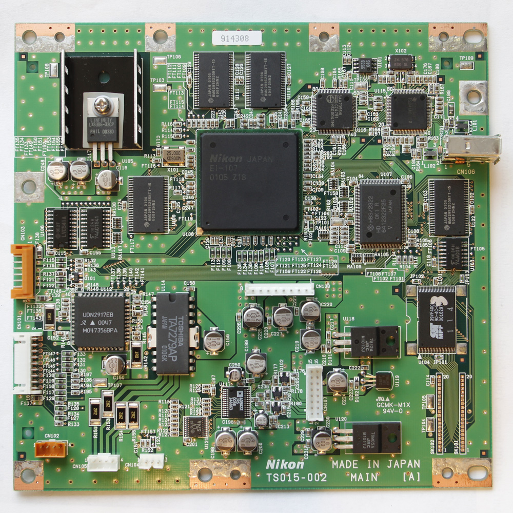
1. Follow steps 1, 2, 5, and 6 in LS-8000 disassembly procedure, or steps 1, 2, 3, 6, and 7 in LS-9000 disassembly procedure. Then disconnect all cables, remove the PCB and remove the metal PCB shields.
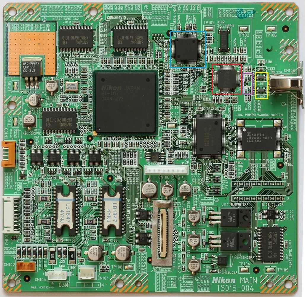
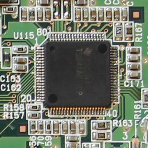
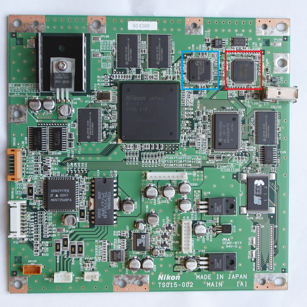
2. The photo above is of the motherboard of LS-9000 scanner. The chip inside the red box is the Firewire controller IC. The IC is made by Texas Instruments, part number TSB41AB1PHPG4.This IC is surface mounted, the package type is HTQFP64. The chip inside the blue box is 1394 SBP-2 link layer controller IC, made by Phillips (NXP), part number SAA7356HL, the package type QFP80.
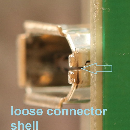
But before you proceed to replacing the firewire controller IC's - first inspect the Firewire connector and few other minor components. I had seen many firewire connectors that were bent open-loose. This is likely to cause a loose contact in firewire ground line and damage the firewire circuitry. I had mostly seen this problem really bad in LS-9000, I do not know exactly why. May be Nikon went with cheaper connectors in LS-9000. For some reason almost every LS-9000 motherboard I get for firewire replacement has a loose (slightly open) shell. I assume a loose shell makes the cable contact intermittent and that may damage the firewire circuitry, (burn the common mode chokes and shunt resistors, kill the firewire controller IC's). See the images below of a damaged (bent open) connector (left). In this case the connector could not be bent back and had to be replaced (right).
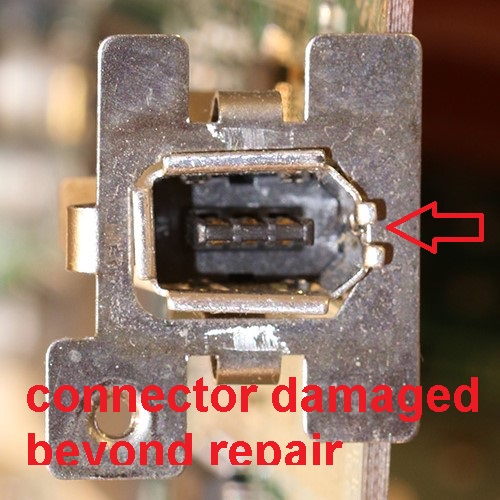
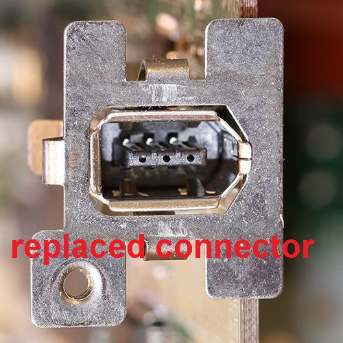
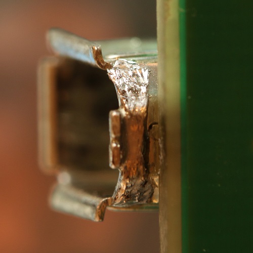
In the cases wheb the connector is slightly open, it can be bent back. In these cases I also tighten and reinforce the shell on these. I squeeze the shell back together (using an alligator clip) and then solder it over with a short piece of copper braid (solder wick) (below, right).
Now, that you have inspected and possibly replaced or fixed the firewire connector, check other firewire components that can be damaged but loose ground line. Those are:
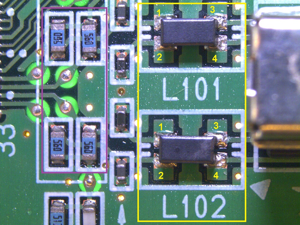
- the shunt resistors R175, R176, R177, and R178 (inside the mahenta rectangle in the photo of the LS-9000 motherboard at the top of the page and in the photo below)
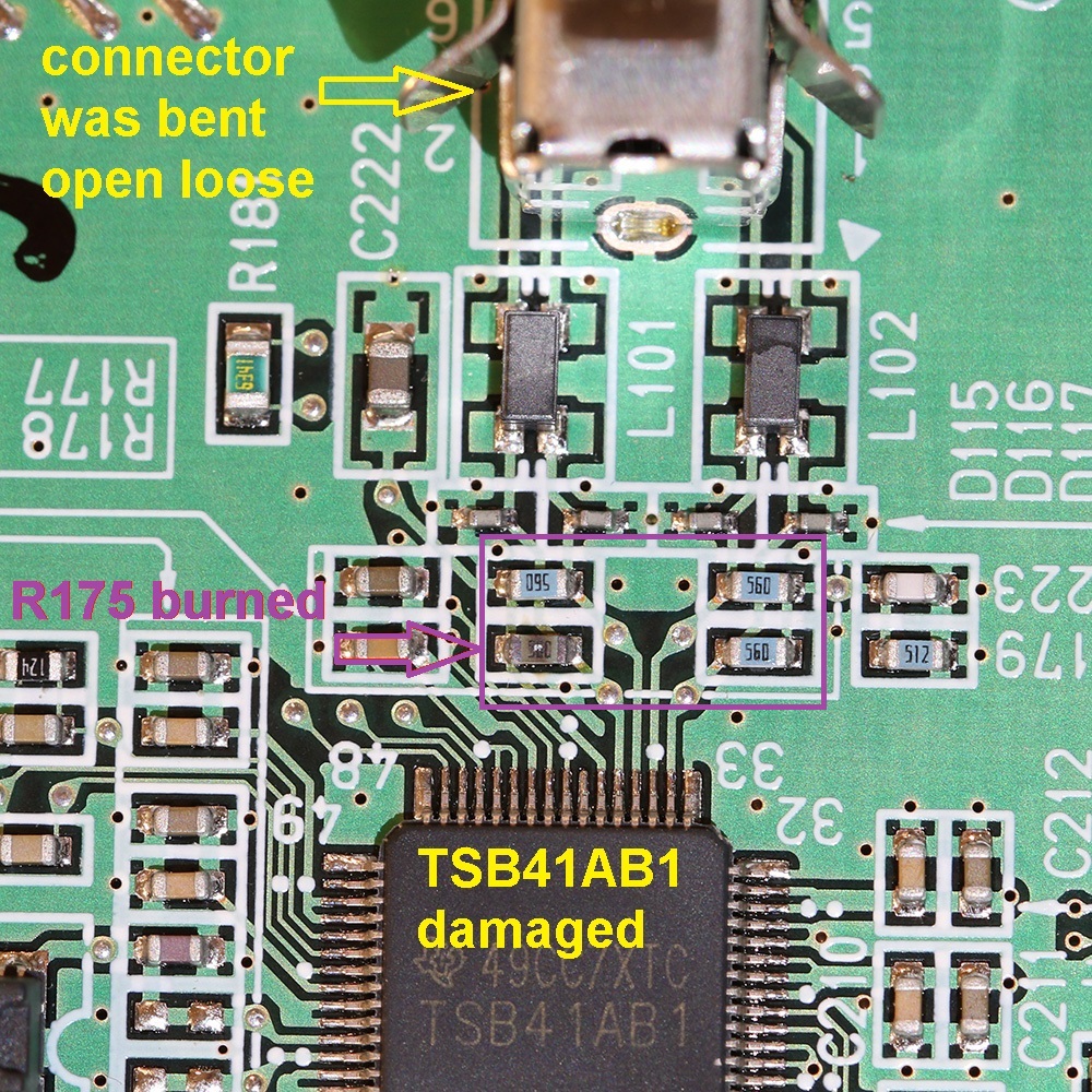
- the common mode chokes L101 and L102 (inside the yellow rectangle in the photo of the LS-9000 motherboard at the top of the page and in the photo below)
I have seen many LS-9000 motherboards with burnt shunt resistors and burnt common mode chokes - either of those will make the firewire communication fail.
If the shunt resistors or chokes are burnt, you will have to replace them. You might still have to replace the firewire IC's as well after that.
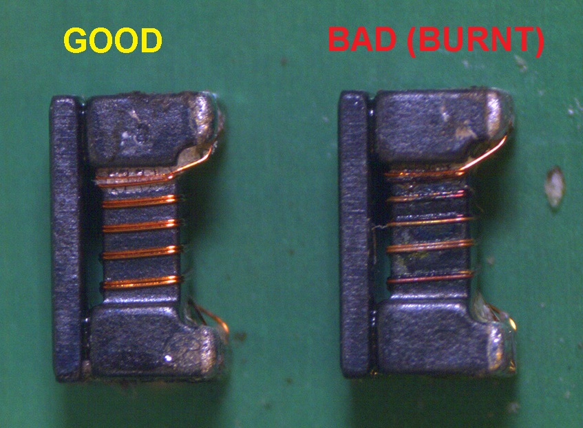
The shunt resistors R175, R176, R177, and R178 are all 56 Ohm. The easiest way to check - use Ohm-meter and test the DC resistance between pads 1-2, 1-3, and 2-4. The resistance between the pads 1-3 and 2-4 should be about 0.4-0.5 Ohm (basically short). The resistance between the pads 1-2 should be about 110 Ohm (two shunt resistors in series through the ground). The common mode chokes burn under current spikes, and they can burn in many different ways - creating opens between 1-3 or 2-4 or shorts between 1-2, see the side-views of the chokes that I had removed from LS-9000 board. Just test them (and resistors) thoroughly.
These common mode chokes are not marked, and I do not have a detailed electrical schematics for either LS-8000 or LS-9000. I had tested the inductance and I believe the closest part is DLW31SN261SQ2 made by Murata Electronics. This choke is listed to have DC resistance of 0.5 Ohm and RF impedance of 260 Ohm at 100MHz.
Note: This part is different than the common mode choke near USB port of LS-50 and LS-5000, which (according to Nikon's repair manual for LS-50) is a Murata part DLW31SN900SQ2 with RF impedance of 90 Ohm at 100MHz.
OK, now back to the firewire IC's...
3. The photo at the top of this page is of the motherboard of LS-8000 scanner. The chip inside the red box is the Firewire controller IC that had most likely failed in the case of the above symptoms. The IC is made by Texas Instruments, part number TSB41AB3.This IC is surface mounted, the package type is QFP80. The chip inside the blue box is 1394 SBP-2 link layer controller IC, made by Phillips (NXP), part number SAA7356HL, the package type QFP80.
Below is the procedure for replacing the TSB41AB3 in LS-8000, the procedure for replacing SAA7356HL is the same. The procedure for TSB41AB1 is very similar - it's just a smaller package.
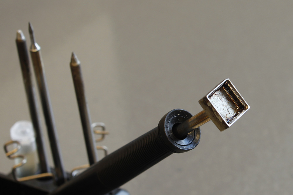
You can remove this IC using a soldering iron with a special tip designed to remove such surface mounted IC's, for example OKI-Metcal SMTC-1115 de-soldering tip (for use with OKI MX-500 or MX-700 soldering station -see below).
If you do not have such de-soldering station, you can very carefully cut each lead with a razor blade (be careful - make sure you cut as close to the plastic IC case as possible and do not cut into the PCB itself) and then de-solder the leads and clean the PCB with regular soldering iron and de-soldering wick.
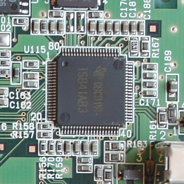
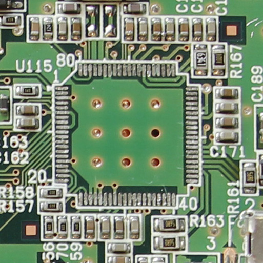
Shown below is a PCB with removed Firewire controller. make sure you clean those contact pads before soldering in a new IC!
Overtime, I had
performed few of these fixes – and had few failures.
I think that unless you are really good at replacing surface-mount components –
the replacement may have weaker thermal contact to the PCB and may get hot after
some time during the operation. If the IC is not rated to work at higher
temperatures this may result in the intermittent failures. The scanner would
work for about 15 min to 1 hour, and then the computer would stop recognizing
it. If I shut it down for an hour and then turn back ON - it would work again –
but then would stop again after some time.
(This may also
indicate initial weak point of the design - the fact that this failure is fairly
common may mean that the chip is not heat sunk sufficiently.)
Assuming that the temperature of the replacement chip was a cause, I started
using the part that is rated to work at higher temperature – up to 85C
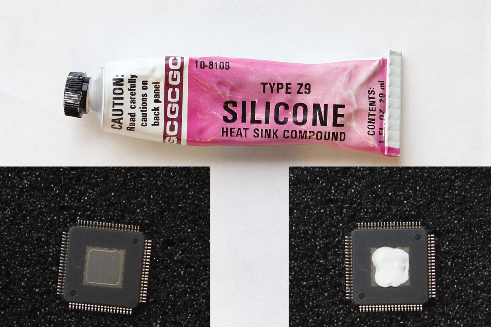
(usual military spec), and also adding a little bit (make sure it is just a little bit!) thermal heat-sinking compound between the replacement IC and the PCB (similar to what they use when mounting heat-sink fans on the processor chips on computer motherboards - see below).
Update: the note above in italic is probably incorrect. I had stopped using military speced components (I could only find them for TSB41AB3 anyway). I think the repeat failures of the past were mostly because I would only replace one IC. Now I always replace both IC's and have far lower repeat failure rate.
I have not had any failures with these – may be I am lucky, may be it is a better IC, or may be I am right :).
Shown below is a PCB with replaced Firewire controller. I am sure you can do a better soldering job, good luck!