![]()
![]()
![]()
![]()
Aligning CCD board in Nikon Super Coolscan LS-8000 and LS-9000 scanners
If the scanned frames are skewed or not properly centered, the CCD board needs alignment.
The procedure is relatively straightforward and is outlined below.
I think any person with reasonable manual dexterity and few simple tools can do it but I cannot assume any responsibility for any damage that can be done to the scanner. You are welcome to follow my procedure, but YOU ARE DOING THIS AT YOUR OWN RISK!
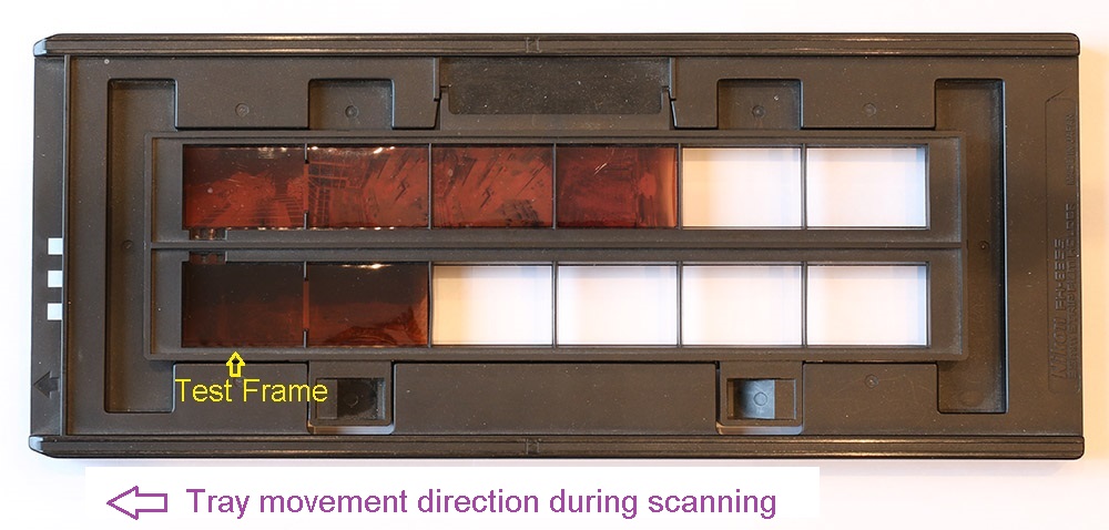
In order to perform the CCD alignment you need to prepare a test frame that is positioned precisely in a film holder, so that you can be certain that the misalignment of the image inside a test scan is due to the CCD misalignment, and not because of the film being sifted. For that reason I would not use FH-835M or FH-869M because they do not precisely define the film position.
I use FH-835S film holder as shown below:
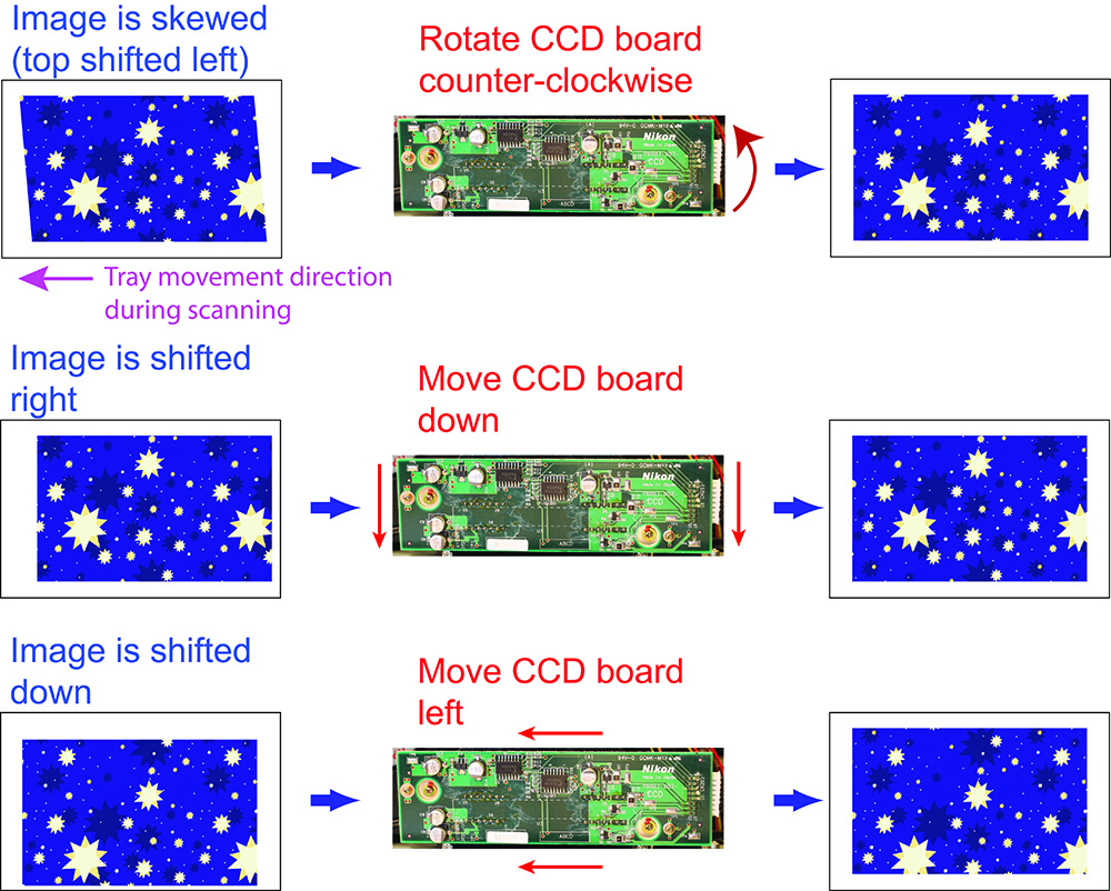
The cheat sheet below shows how the CCD board needs to be moved to correct the image distortion or misalignment. Keep in mind that if you use a different film holder, like FH-835M, the position of 35mm frame will be different.
Here is the procedure. The photos below are all taken on LS-8000, the procedure is identical for LS-9000 except for the disassembly steps.
First take the top shell off and then remove the back panel (perform disassembly steps (1) and (5) for Nikon Coolscan LS-8000 or steps (2), (3), and (6) for LS-9000).
1) Position the scanner (with top shelf and back panel removed) in a clean area. The scanner needs to be connected to both power and computer.
You will need to take scans after every alignment step. You will have to turn the scanner OFF between the alignment steps.
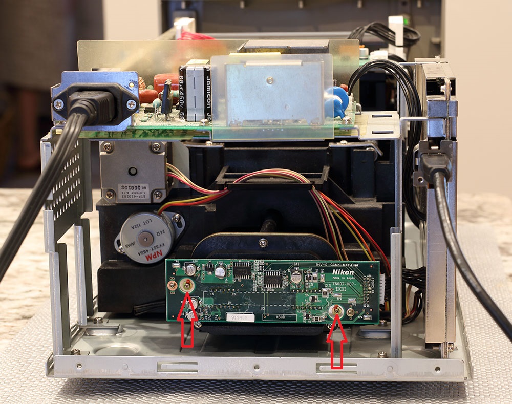
The red arrows in the photo below indicate the screws that hold the CCD board. You will need to loosen them slightly so that you can nudge (or rotate) the board.
Do not loosen these screws too much, because the CCD board movements you need will be very small (I move the board by about 0.2mm at every iteration).
2) Take a test scan. See the scan below, I added a blue border to the scan edges, so that it is easier to see the frame misalignment.
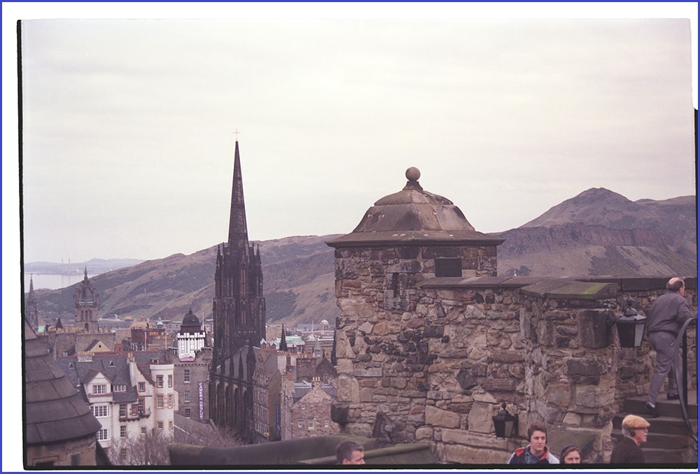
As you can see:
- the image is skewed (easy to see - the right side of the scan is not parallel to the right border of the image)
- the image is shifted left
- the image is shifted down.
According to the cheat sheet above, in order to correct this skew I need to rotate the CCD board counter-clockwise.
3) Powered down the scanner. Then I rotated the CCD board by loosening the right screw and pushing the right side of the board upwards by about 0.2 mm (should have pushed the left side of the CCD board down by 0.2mm instead!).
Powered the scanner back ON, took a test scan:
The skew is smaller (but is still here), but the image is also shifted to the right and to the bottom.
4) Powered down the scanner. Then moved the CCD board by loosening both screws and pushing the CCD board up and left while also rotating counter-clockwise slightly.
Powered the scanner back ON, took a test scan:
Better! Still a little skewed, but centered (left-right) properly and just a little bit down.
5) Powered down the scanner. Then rotated the CCD board just a little bit more and also shifted it left by about 0.2 mm.
Powered the scanner back ON, took the a test scan:

Looks OK now.
6) Tighten the screws a bit more and add a little bit of nail polish (use toothpick!).

Re-assemble the scanner
Good luck!