![]()
![]()
![]()
![]()
Disassembly of Nikon Super Coolscan LS-4000 ED scanners (and some repair suggestions)
Disassembly are shown here for LS-4000, for LS-5000 follow similar steps.
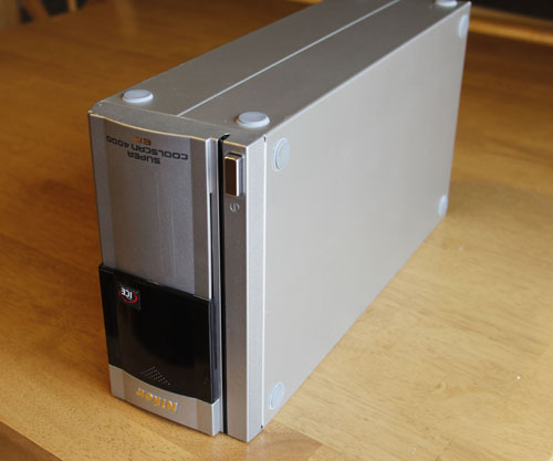
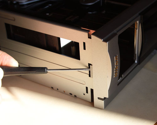
1) Unplug the power & Firewire cable and remove adaptors. Set the scanner upside down on a clean area. Set it upside down if you are planning to inspect/clean the mirror.
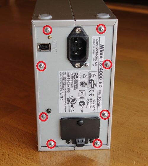
2) Remove these 8 screws on the back of the unit. Take both sides of the outer shell off.
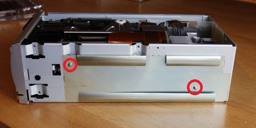
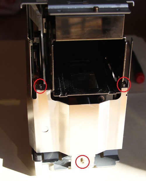
3) Remove these 2 screws and take the first shield panel off.
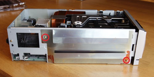
4) Remove these 2 screws and take the second shield panel off.
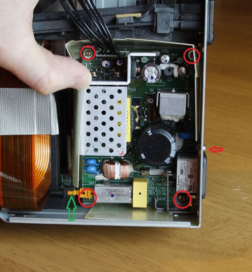
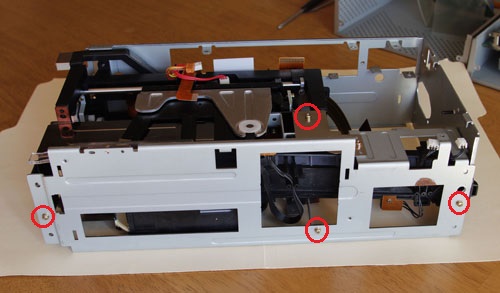
5) Remove these 5 screws (4 circled and one on the back panel - red arrow above is pointing at it). Unplug the black 8-lead cable connecting the power supply to the main board and lift the power supply out. First disconnect it from the plastic power arm at a point indicated by a green arrow - just pull that side power supply up while holding the black side with a screwdriver. After that remove the plastic isolation cage out as well.
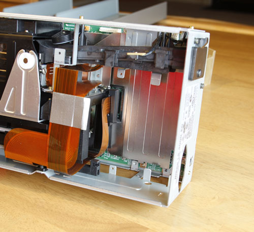
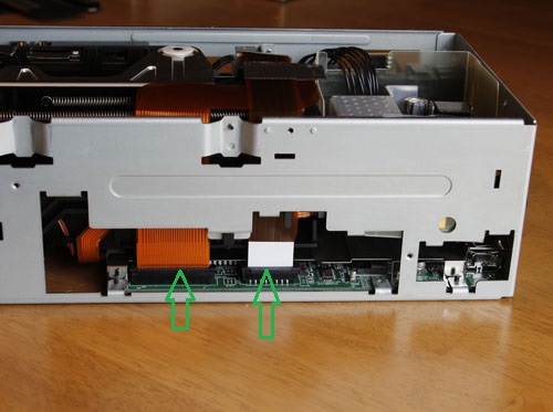
6) With power supply and plastic cage out, you can see the back of the main board and a flex cable connected to the center of the main board, as shown above. You will need to disconnect all cables connected to the main board. Some of them are simple Molex connectors, some are flex connectors. Be careful when disconnecting the flex cables. To disconnect the flex cable, you need to pull up the pressure bracket first, and then gently pull on the flex cable. You never need to apply much force with flex cables - and make sure you do do not!
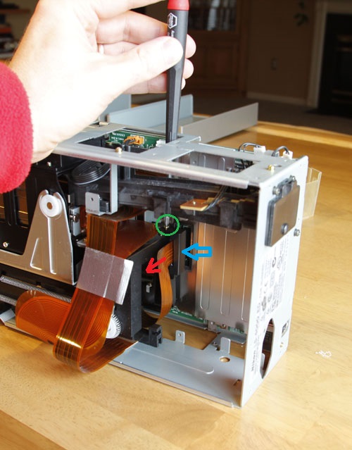
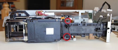
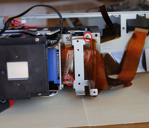
7) Unscrew the screw indicated by a green circle above and remove the housing (indicated by a blue arrow) holding the ferrite bead. Then disconnect the flex cable from the center of the board.
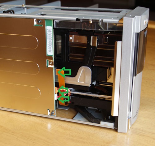
8) Disconnect these three cables (one of then is flex).
9) Disconnect these 2 flex cables.
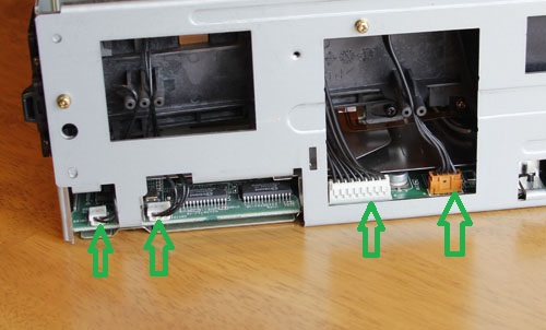
10) Disconnect these 4 cables (you may have already disconnected the 9-lead cable - that is the one that goes to the power supply).
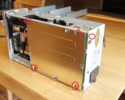
11) Remove 4 black screws on the back of the main board and one screw from the back of the scanner (the screw holding the IEEE-1394 socket). Take the main board out.
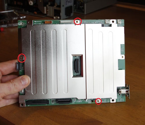
12) This is the main board. If you are replacing the IEEE-1394 controller IC you will need to remove the 3 screws above.
13) Remove the front panel by gently prying the plastic tab near the top of the scanner. Be careful - these are fragile.
14) Remove these 3 screws and remove the shield.
15) Remove these 4 screws and take the top steel bracket off.
16) The big black part labeled PC-GF20 is the LED source. This parts sometimes fails. The good news is that the same part is used for LS-40 (aka IV), LS-4000, LS-50 (aka V), and LS-5000. So you can buy used LS-40 on e-bay and have a fairly inexpensive replacement part. The bad news for LS-4000 owners is that you have to disassemble it this far to get to the LED source. Nikon modified the design for LS-5000 so you do not need to go nearly this far in disassembly to be able to replace the LED source.
If you are repairing the scan head gears, proceed by removing the two black screws above and taking the film conduit out.
17) Remove these 2 screws and take the small steel bracket out.
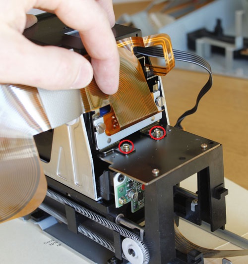
18) Remove these two screws
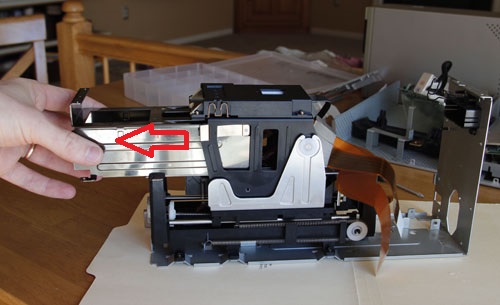
19) Gently pull the scan head out. Careful to feed the flex cables to make sure they do not get damaged.
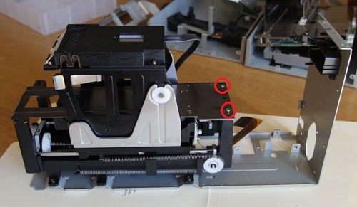
20) Remove these two screws and take the anodized steel black plate out.
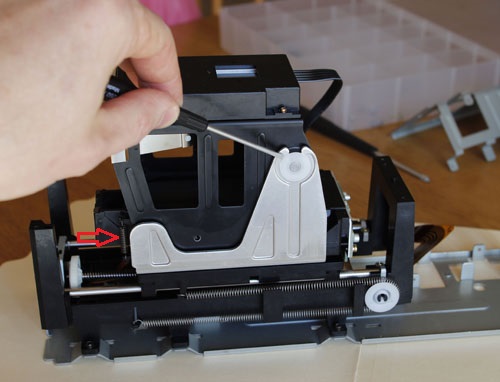
21) Remove two white plastic clips holding the carriage. Also, remove the spring indicated by a red arrow. Then take the carriage out.
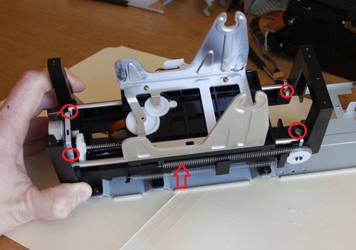
22) Almost there! Remove 4 screws and the spring indicated by the red arrow. Lift the carriage with the guide rods.
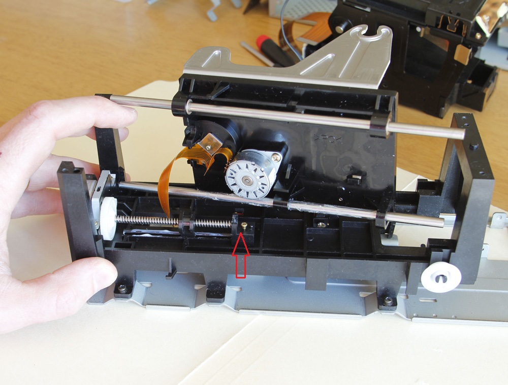
23) Now you can see the worm drive mechanism. As you can see, the worm shaft is held on one side (near the front of the scanner) by the steel plate. the back side should be held by a plastic part, which is missing here (place indicated by a red arrow). The good news is that the same part is used for LS-40 (aka IV), LS-4000, LS-50 (aka V), and LS-5000.
Update. I have taken accurate measurements of both back
support and worm gear slider for these scanners and had them printed on a 3D
printer. Write to me if you need them at
![]() .
.
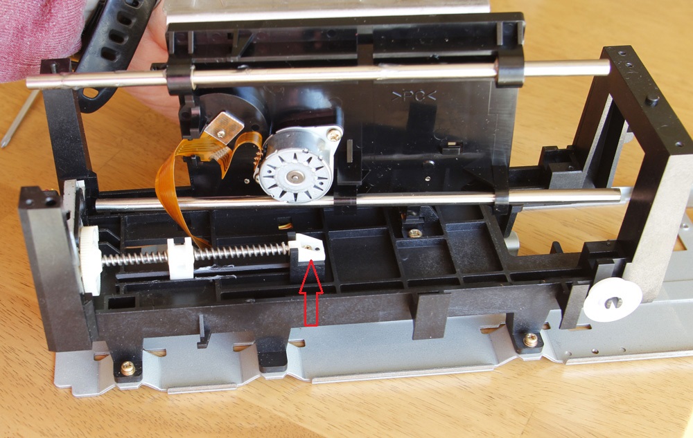
24) The picture above shows the same mechanism for LS-40. You can immediately see that the worm screw has a different pitch. But the plastic back support is the same. Take it out and use it to repair your LS-4000 or LS-5000! Reassemble in the reverse order.