![]()
![]()
![]()
![]()
Replacement of the sensors in SA-21 (or SA30) adapters.
Nikon SA-21 and (SA-30) film strip (roll) adapters use proximity sensors to detect the leading edge of the film strip (roll) and the edges of the frames within a strip. These detectors have limited lifespan (I think the LED’s in them age) and the adapter may start failing. Typical symptoms may be one of following:
- The adapter does not readily grab the film when you insert it.
- The scanner reports that it cannot detect the film after it was inserted.
- The scanner reports that it cannot eject the film
- The scanner seems to work scanned frames are not properly centered within their image files.
The solution is to replace the proximity sensors. I found the original procedure procedure here. It has great deal deal of details, so if you are curious - read it there. Here I reproduce the replacement procedure just in case if the original post disappears.
I think any person with reasonable manual dexterity and few simple tools can do it but I cannot assume any responsibility for any damage that can be done to the scanner. You are welcome to follow my procedure, but YOU ARE DOING THIS AT YOUR OWN RISK!
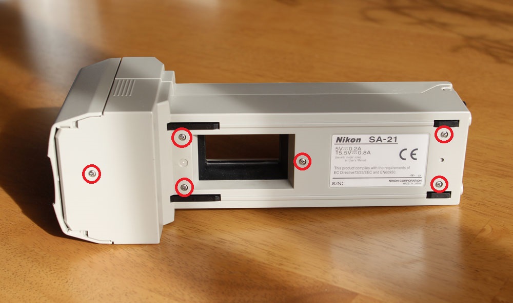
1) Set the Nikon SA-21 on a clean area. Remove these 8 screws on the back of the unit.
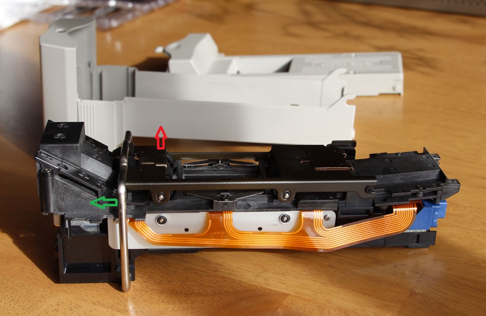
2. Open the adaptor. Push the locking bracket to open position (green arrow), and hinge up the top roller assembly (the bridge) to vertical position (red arrow). When reassembling, the orientation of the locking bracket is not important as it is symmetric. All you will need to remember is that it is the right way around, has to be loaded first into the tilt limit guides, so that it will then later fit into its pivot point socket. This is not very difficult.
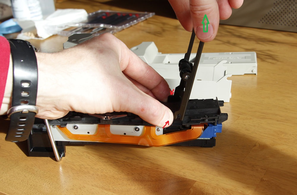
3. Squeeze the plastic tabs (red arrows) and disconnect the top roller assembly (green arrow).
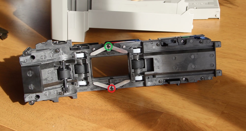
4. Loosen by few turns the screw indicated by the green circle and remove the screw indicated by the red circle.
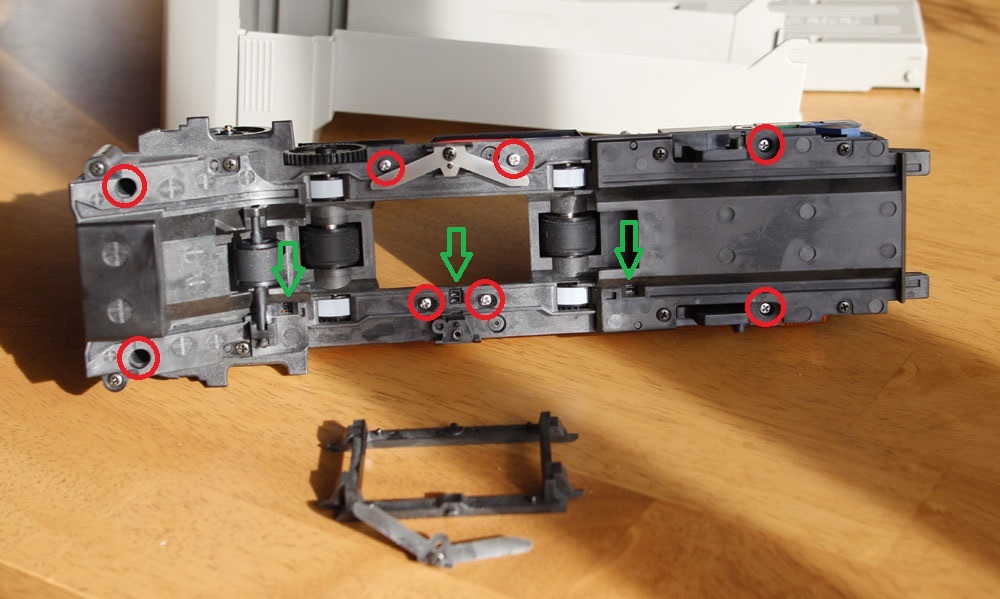
5. Remove the little black plastic bracket. Remember the way is was sitting - it has two tabs and they are not the same thickness - you will have to put it back the same way later. You can now see the sensors - indicated by green arrows. But we will need to disassemble further get to them.
6. Remove 8 screws indicated by the red circles.
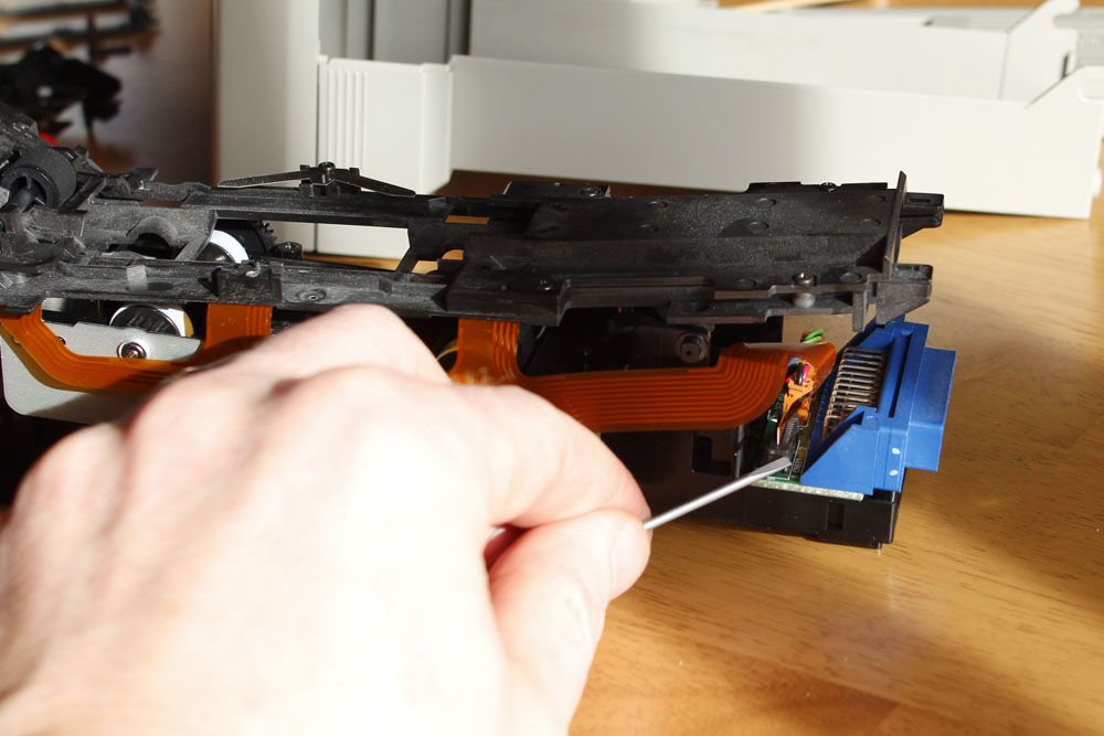
7. Disconnect the flex cable by lifting the pressure bracket on that connector.
8. Lift the top part and place it upside down.
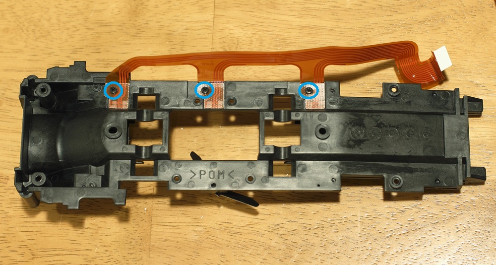
9. Remove three screws indicated by the blue circles and disconnect the flex cable with sensors.
10. Now you can access the sensors. Note the location of the key in the original sensors. It turns out that the replacement part have a different key location - do not get confused by this.
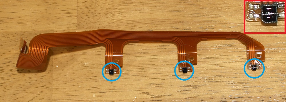
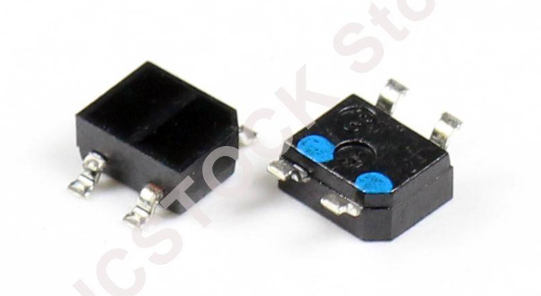
11. I used Panasonic CNB10010SL sensors, as was recommended in the original post. You can no longer buy them at Digi-Key/Mouser, but they are available on e-bay. Below is the stock photo from e-bay seller:
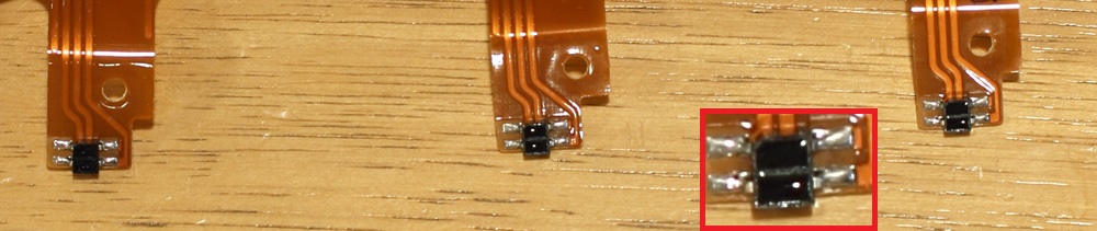
12. Replace the sensors. Below is a photo of the flex assembly with the sensors replaced. Notice that the key location is different.
At this point, as you have the part disassembled, you may consider doing SA-21 to SA-30 conversion, as described here.
13.
Reassemble in the reverse order.
Helmut Stöpfgeshoff points out on his
website, that
you need to make sure you do not tighten all screws as tightly as they were
beforehand. The screws were originally tightened by a high speed machine, which
caused them to become quite hot. Because of this heat, the screws had been
slightly melted into their fitting points. This explains why they felt so tight
to unscrew. He also recommends thoroughly dusting down all components before
putting the adaptor back together. Make sure that you only use a very soft brush
or blower when doing this. Be particularly careful when dusting the lens of the
light-sensors.